Rendering Pipline Introduction
I have written a note about this topic last year, but that was in Chinese, as I’m rewriting my blog in English, I think it’s necessary make a translation as this one is so important. It is probably the last blog before the end of my this semester examination.
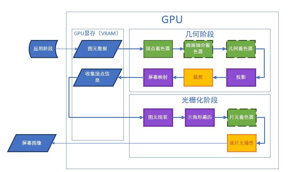
The graphics pipeline can be roughly divide to three steps:
- Application
- Geometry
- Rasterization
There is a image of rendering pipeline, it is so perfect but I cannot found the English version of it:
Application Step
This step runs in CPU and fully programmable. In Unity, we use struct appdata_t to declare what kinds of data we want to obtain from CPU, and pass to GPU, this structure typically includes:
- Position.
- Tangent.
- Normal.
- At most 4 texture coordinate, which is known as UV coordinate.
- Color
Geometry Step
This step runs in GPU and includes many sub-steps, some of them are programmable, some of them are configurable, and some of them are unnecessary.
Draw Call
This is not a sub-step but also an important thing to know. Draw calls are instruction for rendering, every time CPU send a batch of mesh vertex data to GPU, it will also send a draw call with it to tell GPU how to process the data.
Here comes a problem, as we know GPU is way faster than CPU, so if there is a large number of batches, CPU will waste a lots of time in sending data and draw call and GPU will waste a lots of time in waiting. The solution is batching, merge many small draw call to a bigger one, there are two implementation in Unity:
- Make game object static, all static object will be submit in one draw call.
- Identical objects that are created dynamically will be submit in one draw call, but comes with many restriction, for example, a simple rescale will affect the batching and create a new draw call.
Vertex Shader
The first step in the Geometry step, it is fully programmable and necessary.
In this step each vertex will be treated separately, we can do such as position transformation and color information processing (just calculation some color information, not coloring) in this step.
The pipeline also do camera transformation in this step.
Tessellation Stage
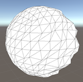
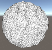
Fully programmable and unnecessary. In this step programmer can add more vertices based on the vertices they already have.
Geometry Shader
Fully programmable and unnecessary. In this step programmer can add, delete and modify vertices, but the efficiency of modification is much lower than Vertex Shader.
It will also classify vertices into three arrays:
- triStream
- lineStream
- pointSteam
Points will be assembled to corresponding shapes in Primitive Assembly step.
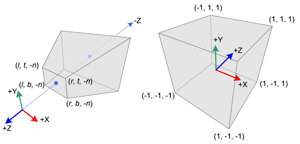
Projection
Not programmable and necessary. In this step GPU transform vertices from camera space to clip space based on one of two methods by transform a frustum to clip space (for more information about clip space), the frustum is the area that camera select to see, it includes squeezing the frustum and move the origin:
There are two alternative for selecting the area:
-
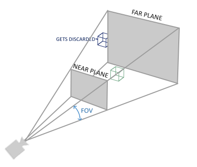
Perspective Projection: Define a frustum, GPU only rendering objects that inside the frustum. When defining the frustum we need to consider the Far Clipping Plane, Near Clipping Plane, Field of View.
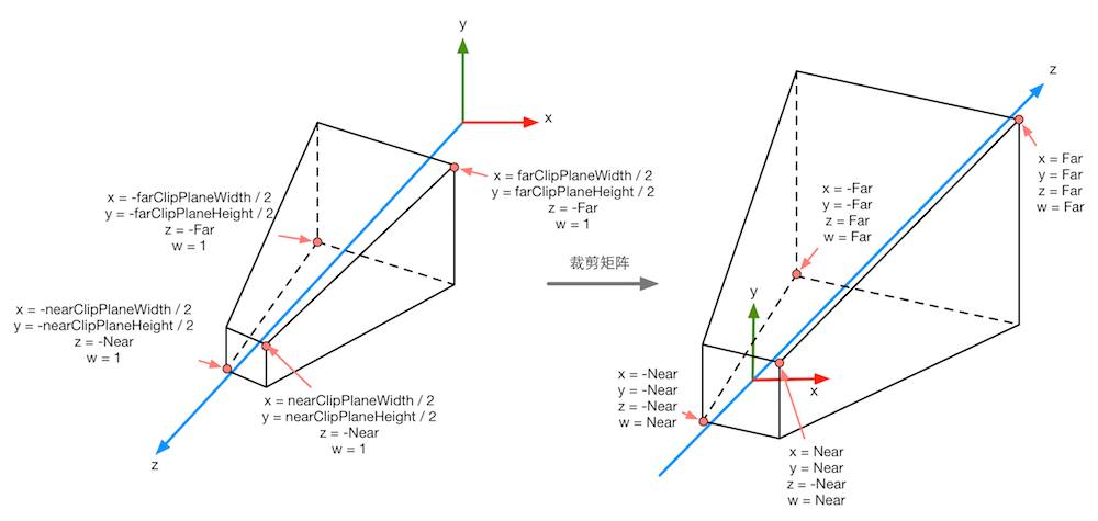
The clip space of perspective projection is on the right
-
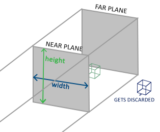
Orthographic Projection Matrix: The frustum will be a cuboid in this case and we need to consider the Size of it.
The clip space for perspective projection and orthographic projection looks different, but both of them have properties that the objects inside frustum has $x,y,z\in [-w,w]$, The transformation matrix will be introduced in another blog.
Clipping
Configurable and necessary. Remove vertices that are outside of the frustum and transform it into a cube (Normalized Device Coordinates, any point in NDC has $x,y,z\in [-1,1]$), for orthographic projection, its already in NDC, for perspective projection, we need to perform perspective divide, that is $x,y,z=\frac{X}{w},\frac{Y}{w},\frac{Z}{w}$. The NDC transformation is usually after clipping, but some people suggest it in reverse, both of them make sense.
Screen Mapping
Since GPU already have the Normalized Device Coordinates, the next step is just map them into the screen. $x$ and $y$ are used directly, $z$ will be stored for depth test.
Rasterization Step
Primitive Assembly
Configurable and necessary. Assemble points according to the output of Geometry Shader.
Triangle Traversal
Configurable and necessary. For each pixel, check if it is bounded by any triangle, we generate a fragment for a group of pixels that is bounded by the same triangle. For those pixel that partly bounded by a fragment, we have following solution:
- Standard Rasterization
- Outer-conservative Rasterization
- Inner-conservative Rasterization
This step also involve contents such as anti-aliasing and Depth Interpolation Calculation (Color calculation scheme for pixels cover by multiple triangles).
Fragment Shader
Fully programmable and necessary. Determine color for each fragment, for pixels whose color we don’t know, a common approach is using linear Interpolation, calculate the color from its adjacent vertices.
Per-Fragment Operations
Configurable and necessary. In this step we apply operation on each fragment (including testing and merging).
Scissor Test
Basically is 2D clipping, programmer can declare a clipping frame, only fragment that inside the frame will be displayed.
Alpha Test
API is Abandoned, only fragments whose alpha value larger than the threshold will be displayed.
Stencil Test
In this test, we have a stencil buffer, which is a mask that cover the whole screen, for each run of render, we can design a batch of rules that rewrite the buffer, or only render model follow some stencil value comparison rules (such as bigger, smaller, equal or always).
Depth Test
Depth testing allows programmers to set the occlusion relationships between rendered objects. Typically a lot of objects need to be culled in this step, so here comes a technology that can bring the depth test forward, early-z, however, it can only be used with opaque object because it conflicts with alpha test (when closer object has alpha value 0).
Merge
After all these test, GPU will merge the color of fragments into pixels. There are two method in common, one is replace directly, one is doing arithmetic calculation on fragment color (multiplication, addition).